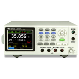
- Description
- Specifications
- Documents
- 50,000 Counts Display
- 3.5” (320x240) TFTLCD Display
- High Accuracy of 0.05 %
- 1Amp Test Current, 0.1 μΩ Resolution
- Fast measurement of 60 readings per second
- Four wire resistance measurement
- Temperature Compensation measurement function
- Delayed measurement
- 20 sets of panel setting memory
- Dry circuit testing
- Drive Modes: T3MIL50X: DC+/DC-, Pulsed, PWM, Zero, Standby T3MIL50: DC+, Standby
- Interface: USB Device, RS-232C, Handler/Scan/EXT I/O
Teledyne Test Tools series of D.C. Milli-Ohm meters offer two models T3MIL50 and T3MIL50X, which features a 3.5-inch TFT display with a measurement accuracy of 0.05%, maximum 50,000 count measurement display and sampling rate of 60 readings per second. The T3MIL series also provides four wire measurement as well as temperature measurement and temperature compensation functions to meet the requirements of low resistance measurement applications.
T3MIL50X provides Dry circuit and various drive modes (DC+, DC-,Pulsed, PWM) for measurement applications on different materials. The pulsed current output mode is suitable for interacting conductors of different materials to reduce the influence of thermal EMF on the measurement. Thermal EMF is caused by electric potential difference generated from different conductors acting on different temperatures while conducting low resistance measurements. The DC+ and DC- output modes are best for the measuring of inductive components. The PWM output mode is suitable for measuring temperature sensitive materials to avoid any resistance variation caused by measurement current being applied for a long period of time. Dry circuit testing is used to detect contaminates and oxides on mating contact surfaces. Typically, a dry circuit test is performed in conjunction with environmental stress tests intended to create contamination or metal oxides on connector contact surfaces. Excessive current through the contacts during testing can cause a physical change in the contact area on a microscopic level. Current can cause heating, which can soften or melt the contact points and surrounding area. The contact area enlarges, resulting in a reduction in resistance. To avoid “wiping away” the contaminates, a dry circuit method is used for testing. A dry circuit is one in which the voltage and current are limited to levels that can't cause changes in the physical and electrical condition of the contact junction. Generally, the open circuit voltage is 20 mV or less and the short circuit current is 100 mA or less. The Dry circuit measurement can also be made in DC+, DC- and Pulsed modes.
